You’ve invested in a top-tier induction heating system—but if your induction heating coil is poorly designed or mismatched to your application, you’re leaving 30% of its efficiency (and profit) on the table. From uneven gear hardening to frequent coil burnout, the wrong coil causes rework, downtime, and wasted energy. The truth? The induction heating coil isn’t just a “part” of your setup—it’s the heart of energy transfer, dictating part quality, process speed, and operating costs.
In this definitive guide, we’ll demystify induction heating coils: how they work, how to choose the perfect one for your workpiece, design secrets that boost performance, and simple maintenance to double their lifespan. Whether you’re annealing wires, forging steel, or hardening automotive parts, this guide turns coil confusion into competitive advantage.
What Is an Induction Heating Coil, and How Does It Drive Your Process?
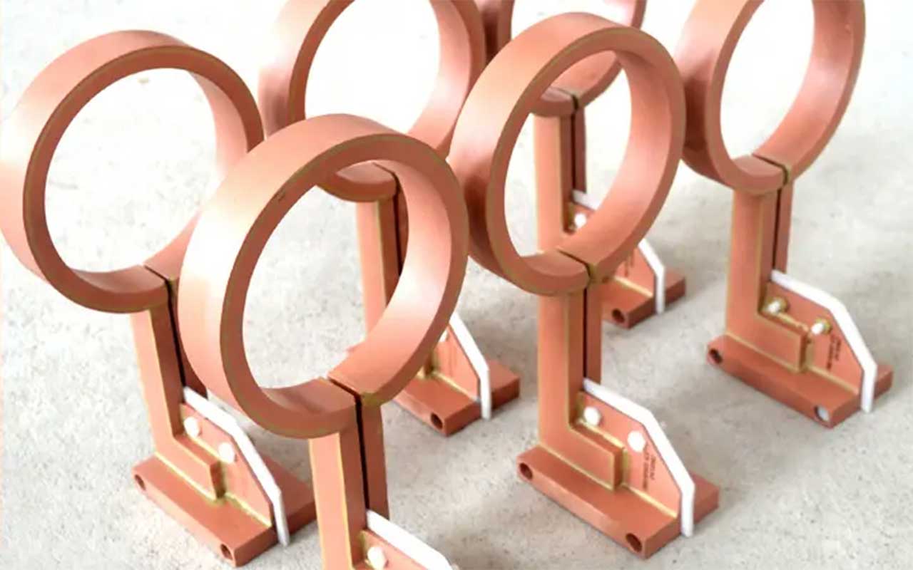
An induction heating coil is a water-cooled copper conductor (typically pure copper tubing) formed to match the shape of your workpiece. It acts as the bridge between your induction power supply and the material you’re heating, using electromagnetic principles to generate heat directly inside the workpiece—no direct contact required. Here’s the step-by-step science:
-
Electromagnetic Field Generation: When alternating current (AC) from your power supply flows through the copper coil, it creates a rapidly oscillating magnetic field around the coil.
-
Eddy Current Induction: This magnetic field penetrates the conductive workpiece (steel, aluminum, copper), inducing tiny “eddy currents” to flow within its surface.
-
Joule Heating: The eddy currents encounter the workpiece’s electrical resistance, converting electrical energy into heat. This is called Joule heating, and it’s why the workpiece heats up—while the coil itself stays cool (thanks to internal water cooling).
-
Precision Control: The coil’s shape, size, and the frequency of the current determine where and how heat is generated. For example, a contoured coil ensures uniform heating on a gear’s teeth, while a solenoid coil delivers consistent through-heating for forging.
Critical Misconception: Many manufacturers blame their power supply for slow heating—9 times out of 10, the issue is a mismatched coil. A coil that’s too large, too small, or made with the wrong material can cut energy transfer efficiency by half.
Anatomy of a High-Performance Induction Heating Coil
Not all induction heating coils are built the same. A durable, efficient coil consists of five key components, each playing a non-negotiable role in performance . Skipping quality in any part leads to premature failure:
-
Connection Cartridge: The “link” between the coil and the power supply’s transformer. Direct-mount cartridges work for small 200kW+ systems (gears, small shafts), while auxiliary cartridges extend reach for large parts (bed frames, axle) and boost compatibility across machines .
-
Bus Bar: Conducts current from the cartridge to the sensing conductor, adding structural strength. It’s often made of thick copper to minimize energy loss.
-
Sensing Conductor (Coil Core): The star of the show—this is the copper tubing that forms the coil’s shape. Hollow pure copper is ideal: it’s highly conductive, lightweight (thanks to the skin effect, current stays on the surface), and easy to form . Rectangular tubing is preferred over round for most applications, as it maintains uniform gap with the workpiece and simplifies cooling hole machining .
-
Cooling Accessories: Water channels and spray nozzles built into the coil. They cool the coil itself and (in many cases) deliver quenching media directly to the heated workpiece—streamlining the process .
-
Magnetic Conductor: A hidden hero that focuses the magnetic field onto the workpiece (instead of wasting it in the air). This boosts heating efficiency by up to 25% and reduces energy consumption .
How to Choose the Right Induction Heating Coil (5 Step Framework)
The best induction heating coil for your operation depends on three variables: your workpiece (shape, material, size), your process (hardening, annealing, forging), and your power supply. Follow this framework to avoid costly mismatches:
Step 1: Define Your Workpiece & Process Goals
Start with the end in mind. Ask: Where do I need heat? How deep should the heat penetrate? For example:
-
Surface Hardening (Gears, Shafts): Need localized heat on the surface (0.1–3mm depth). Choose a contoured coil that mirrors the workpiece’s shape (e.g., tooth-shaped for gears) to maintain a 1–3mm gap—critical for uniform heating .
-
Through-Heating (Forging, Melting): Heat must reach the core. Opt for a multi-turn solenoid coil and low-frequency power (1–10kHz) .
-
Internal Heating (Bore Holes): Use a small-diameter “internal bore coil” designed to fit inside the hole, paired with high frequency .
Step 2: Match Coil Material to Your Needs
Copper is non-negotiable for conductivity, but not all copper is equal:
-
Oxygen-Free Pure Copper: The gold standard. It offers superior conductivity and structural rigidity, making it ideal for high-volume, high-temperature applications (e.g., automotive part hardening) .
-
Insulated Copper: For applications where electrical interference is a risk. Look for coils wrapped in double glass wire that withstands -10℃ to 400℃ .
Step 3: Choose the Right Coil Shape
Shape dictates heating uniformity. Here are the most common designs and their best uses :
|
Coil Shape
|
Best Applications
|
Frequency Range
|
|---|---|---|
|
Solenoid (Helical)
|
Shafts, pipes, through-heating for forging
|
Low-Medium (1–50kHz)
|
|
Contoured
|
Gears, complex automotive parts, localized hardening
|
Medium-High (10–100kHz)
|
|
Pancake (Flat)
|
Flat surfaces, shrink fitting, soldering
|
Medium-High (50–200kHz)
|
|
Internal Bore
|
Hole hardening, internal annealing
|
High (100–400kHz)
|
Step 4: Optimize for Your Power Supply
Coil size and turns must align with your power supply’s frequency and output:
-
High Frequency (100–400kHz): Use thin, single-turn coils for surface heating (e.g., annealing wires) .
-
Low Frequency (1–10kHz): Use thick, multi-turn coils for deep penetration (e.g., forging) .
-
Power Density: For fast, high-temperature processes (e.g., brazing), choose a coil with higher power density (more copper per square inch) .
Step 5: Prioritize Cooling System Compatibility
A coil without proper cooling burns out in hours. Ensure the coil’s cooling system matches your setup:
-
Water Pressure: Most coils require 0.3–0.4MPa water pressure . If your system runs lower, choose a coil with larger cooling channels.
-
Quenching Integration: For heat treatment, look for “self-spraying” coils that combine heating and quenching—this eliminates extra equipment .
5 Pro Tips to Extend Induction Heating Coil Lifespan (Save 50% on Replacements)
A well-maintained induction heating coil can last 2–3x longer than a neglected one. Follow these expert practices :
-
Clean Conductive Surfaces Regularly: The coil’s connection to the transformer collects dust and oxidation, increasing resistance (and energy waste). Wipe it with a soft cloth monthly and reapply silver plating annually to prevent corrosion .
-
Use the Right Bolts & Torque: Secure the coil with stainless steel or brass bolts (pure copper threads strip easily). Tighten to 155–178N for M8 bolts—too tight breaks the sleeve, too loose causes arcing .
-
Monitor Cooling Water Quality: Use filtered, deionized water to avoid mineral buildup in cooling channels. Buildup blocks flow, leading to overheating and burnout .
-
Inspect for Physical Damage: Check for bent tubing or cracked insulation before each shift. A small leak or kink can escalate to a catastrophic failure mid-production .
-
Store Coils Properly: Hang coils vertically (don’t stack them) to prevent bending. Keep them in a dry, dust-free area to avoid corrosion .
Real-World Impact: How the Right Coil Transformed Two Manufacturers
Numbers tell the story best. Here’s how optimizing induction heating coils drove tangible results:
Case 1: Automotive Gear Manufacturer
Challenge: 15% of gears failed quality checks due to uneven hardening; coils burned out every 2 weeks. Solution: Switched to contoured, rectangular-copper coils with magnetic conductors. Result: Defect rate dropped to 0.5%; coil lifespan extended to 8 weeks; energy costs fell by 18% .
Case 2: Aerospace Shaft Forger
Challenge: Slow heating times (45 minutes per batch) with a generic solenoid coil. Solution: Upgraded to a multi-turn, low-frequency coil matched to their 50kW supply. Result: Heating time cut to 12 minutes per batch; production capacity tripled .
Final Thoughts: Your Coil Is Your Competitive Edge
An induction heating coil isn’t a commodity—it’s a precision tool that directly impacts your bottom line. By matching the coil’s material, shape, and design to your workpiece and process, you’ll eliminate rework, slash energy costs, and boost throughput. And with simple maintenance, you’ll avoid unexpected downtime that derails production.
Still unsure which induction heating coil is right for your application? Leave a comment below with your workpiece details (material, shape, process), and our coil experts will send you a personalized recommendation—free of charge.
